




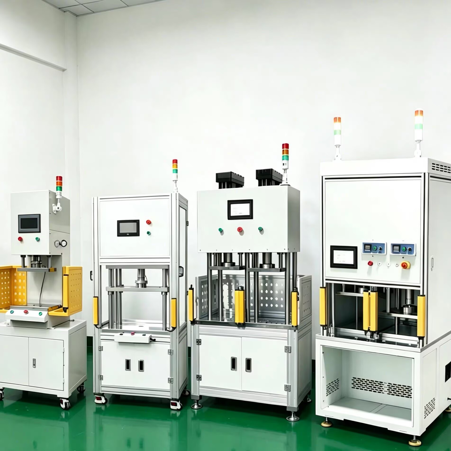
PUMO servo press - scientific selection steps, installation requirements, and daily maintenance
1、 Selection steps
Determine the nominal pressure: Calculate the maximum expected pressing force F_max during the pressing process (including interference fit, friction coefficient, and the influence of introduced chamfers), multiply it by a safety factor of 1.2-1.5 (with an impact load of 2) to obtain the design pressure F_sel, and select it based on the PUMO rated force series (for example, if 8kN is required for calculation, choose 10kN; if 45kN is required, choose 50kN or 63kN). Attention: The servo press should not work continuously at the upper limit of rated force for a long time. It is recommended that the commonly used working force be ≤ 80% of the nominal force.
Determine the stroke and opening height: Effective pressing stroke L_press (displacement of the press head from contact with the workpiece to completion of pressing)+fast clearance (distance from the top surface of the workpiece to the initial position of the press head)+safe clearance for loading and unloading (usually ≥ 20mm)=minimum required full stroke. Opening height=workpiece+fixture+die thickness+safety clearance, confirm the adjustable range of the machine model.
Speed requirement: The fast forward section should be as fast as possible (to increase the beat) → Choose a large lead screw+high-power servo motor; The pressing section needs to be slow enough to ensure the quality of the curve (usually 1-10mm/s, precision parts 0.2-2mm/s) → Confirm that the motor does not lose step at the lowest stable speed. If there is a contradiction between the pressing time and the rhythm, it is possible to consider segmented and multi speed.
Accuracy requirement: ordinary press fit ± 0.01mm, sufficient for repeated positioning; Ultra precision (such as optical components and measuring tool calibration) selection grating ruler full closed-loop ± 0.005mm. The recommended pressure display resolution is ≤ 0.5% FS.
Structural form: Choose C-type/four column/desktop type according to the principles of the fourth article; Unbalanced load or mold election with four pillars.
Process function: Confirm the required speed, whether constant pressure is maintained, whether heating (temperature/power) is needed, whether center ejection is needed, whether dual pressure heads/multi station turntables are needed, and determine the number of windows.
Data docking: Confirm the factory network protocol (Modbus TCP/PROFINET/EtherNet IP/EtherCAT) and MES field requirements (barcode, work order, operator ID, OK NG reason code, etc.).
Safety and certification: CE marking is required to confirm that the grating level, emergency stop button color/position comply with EN ISO 13850, and the STO function requires a safety relay or safety PLC.
2、 Installation requirements
Foundation: It is recommended to fix the C-type landing machine on a plain concrete foundation with a thickness of ≥ 150mm, and tighten the anchor bolts M16-M20 with a levelness of ≤ 0.1mm/m; Table style stable workbench to avoid resonance.
Power supply: three-phase 380V ± 10% 50/60Hz (single-phase 220V for small models), grounding resistance ≤ 4 Ω. It is recommended to install an isolation transformer or a regulated power supply if the power grid fluctuates greatly.
Environment: Temperature range of 0-40 ℃, humidity ≤ 85% RH, no condensation, away from strong electromagnetic interference sources (high-power welding machines, variable frequency furnaces), dust covers or positive pressure air curtains should be added in places with large dust.
Air source (if equipped with pneumatic fixtures/blowing/center ejection): 0.4-0.6MPa clean compressed air, with triple fittings.
3、 Daily maintenance and upkeep
Screw and guide: Add designated high-temperature lithium grease (commonly ISO VG68/100) according to the instructions every 6-12 months or every 5000 hours, and excessive use may cause temperature rise; Add lubricating grease to the four column guide sleeve according to the wear condition.
Force sensor calibration: It is recommended to calibrate with a third class standard force gauge every year or every 20000 press installations (whichever comes first). The HMI provides "zero calibration" and "gain calibration" guides to input the standard force value for automatic calculation.
Safety device testing: Before each shift, manual testing of emergency stop and grating obstruction should immediately slow down and stop the pressure head (STO takes effect), and the two hand buttons should not move if they are not synchronized for more than 500ms.
Inspection of vulnerable parts: Tension and wear cracks of synchronous belt (if any), reliability of limit switch action, and no damage to cable drag chain.
Data backup: Regularly backup formula parameters and judgment window settings; It is recommended to archive the original curves of important batches according to customer requirements.
Fault handling: Common alarms - "force exceeding upper limit" (possibly due to workpiece size deviation/foreign object/sensor drift requiring calibration), "position not reached" (screw slip/mechanical jamming/incorrect stroke setting), "servo alarm" (overcurrent/encoder disconnection check wiring), "grating trigger" (reset after confirming safety with manual intervention). PUMO provides a quick lookup table for alarm codes.
Through correct selection, standardized installation, and regular calibration and maintenance, the PUMO servo press can be stably used for more than 10 years, with a press fit qualification rate of over 99.9%, providing reliable quality gates for intelligent manufacturing production lines.