




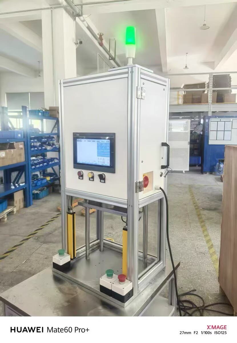
PUMO servo press - detailed explanation of mechanical structure composition and key components
PUMO servo press is a precision electromechanical system that integrates mechanics, electronics, sensing, and software. It mainly consists of the following six modules:
① Body and Guidance System: The C-type body is cast as a whole and undergoes secondary aging and precision machining. The front end forms an "arch" opening, and the throat depth determines the maximum width that can be extended into the workpiece. A T-shaped groove (commonly M12/M16 spacing of 125/150mm) is set below the workbench for fastening the mold/positioning fixture; The four column model consists of a base, four quenched chrome plated guide columns (with a diameter of 40 to 100mm depending on the tonnage), a moving template (Slider), an upper crossbeam (Head Beam), and a locking nut. The moving template moves up and down along the guide columns and is guided by four sets of linear or ball guides. The guide clearance is adjustable, and the parallelism is ensured by scraping or adjusting pads. Some high-precision models add anti rotation key slots between the moving template and the pressure head to prevent the pressure head from rotating. The rigidity of the fuselage has been verified by FEA, and the elastic opening deformation of the fuselage is usually controlled within 0.03mm when fully loaded.
② Servo drive and transmission system: The core is a permanent magnet synchronous servo motor (power 0.75-22kW depending on the model), which is matched with a servo drive that accepts controller commands and executes torque/speed/position closed-loop algorithms. The preferred transmission component is a precision C3/C5 grade ground ball screw (usually with a lead of 5mm, 10mm, 16mm, 20mm), which is pre stretched and installed to eliminate the influence of thermal elongation and apply appropriate pre tightening force to eliminate axial clearance (Backlash Free). The motor rotation θ is converted into a head displacement X=Ph × θ/360 ° (Ph is the lead of the screw). When large tonnage or deceleration is required, a low backlash planetary gear reducer (reduction ratio 3:1-10:1) can be added to increase the output torque. The synchronous belt drive version is used for some C-type machines to reduce axial length and requires regular tensioning.
③ Pressure head and worktable: The pressure head/Ram is an alloy steel part that has been quenched and tempered, with a standard internal thread or quick change chuck interface at the lower end connected to the pressure mold; Non contact proximity switches or photoelectric sensors are installed as hardware limit protection for the upper and lower limits of the pressure head stroke. The surface of the Bottom Platen is hardened and ground flat, with T-shaped grooves/positioning holes/air path holes. It can be optionally equipped with a center ejector, workpiece clamping cylinder, or heating plate (electric heating tube+temperature controller PID, up to 300 ℃).
④ Force detection unit: A high-precision piezoelectric force sensor (Load Cell) is connected in series between the pressure head and the upper connecting plate. The rated range is selected according to the nominal force of the model, with a nonlinearity of ≤± 0.05% FS and temperature drift compensation. The output mV/V signal is converted to ± 10V or digital RS485 through an isolation amplifier and sent to the PLC. The force sensor needs to be calibrated regularly (usually every year or every 5000 hours) with a standard force gauge. PUMO provides a one click calibration guide to automatically calculate the gain and zero offset by inputting the standard force value.
⑤ Displacement detection and coding feedback: In addition to relying on servo encoders to indirectly calculate displacement, some ultra high precision models (with repeat positioning requirements of ± 0.005mm or less or requiring full closed-loop) install independent magnetic grating rulers/grating rulers (resolution of 0.1 μ m~1 μ m) on the pressure head side to directly measure the absolute position of the pressure head, eliminating thermal elongation of the screw and cumulative errors in reverse clearance, forming a fully closed-loop position control.
⑥ Electrical control cabinet and human-machine interface: built-in PLC (Mitsubishi FX/Q series, Siemens S7 1200/1500 or domestic equivalent), servo drive, switch power supply, relay, air switch, safety relay or safety PLC (supporting STO - Safe Torque Off). The HMI is a 7 "/10"/15 "TFT true color touch screen, with interfaces including: main screen (operating status/current force displacement curve/OK NG count), parameter setting screen (formula editing/speed position pressure holding time/judgment window), I/O monitoring screen, alarm history, data query/export screen, and system settings (language/unit/password). Support switching between multiple languages (Chinese/English/Japanese, etc.).
After the assembly of the whole machine, perform factory inspection: first, run the entire process back and forth at rated speed without load to confirm that there is no abnormal noise or jamming; Load calibration force (the deviation of the displayed force value should be ≤ ± 1% FS when compared with a standard force gauge); Pressure fitting accuracy test (repeated positioning 10 times with a standard deviation of σ ≤ 0.01mm); Reproducibility test of force displacement curve; Safety function testing (grating interruption emergency stop, unsynchronized hands without action, over travel limit triggering). Each device is accompanied by a factory inspection report, electrical schematic diagram, list of vulnerable parts, and operation manual.