




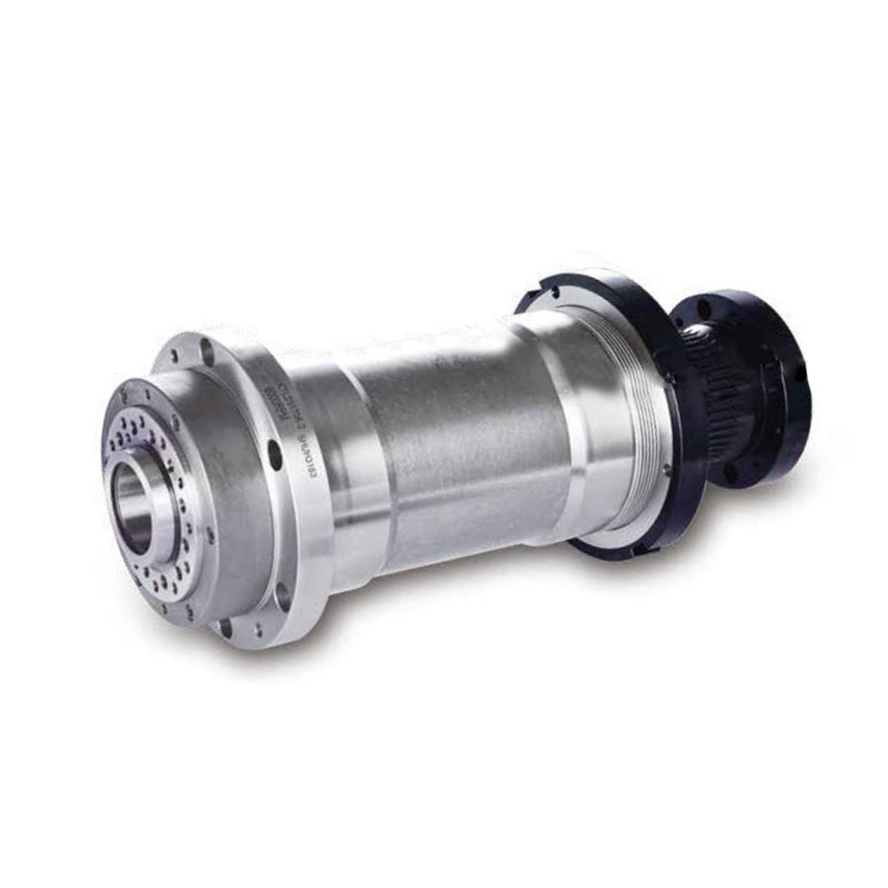
PUMO CNC Machine Spindle - Scientific Selection Steps, Installation Points, and Maintenance Guidelines
The correct selection of PUMO CNC machine spindle requires comprehensive processing technology, machine structure, and cost factors. It is recommended to follow the following steps:
Step 1: Clarify the process requirements
-Main processing materials (steel/cast iron → requiring high torque and low to medium speed; aluminum/copper/graphite → requiring high speed; precision machining of quenched steel → requiring rigidity and thermal stability)
• Typical tool diameter and overhang → Determine required spindle power and torque
• Maximum required speed (driven by precision machining surface quality) and minimum required speed (driven by thread/re cutting)
-Do you need C-axis positioning/rigid tapping/milling combination? → Determine encoder resolution and servo spindle necessity
• Automatic tool change → Determine the form of the puller (BT/HSK/CAT) and the stroke of the slack puller
Step 2: Determine the transmission form
Heavy cutting, high torque universal machining → Belt transmission; Need to balance good low-speed stability and high speed → direct drive; High speed precision/high gloss/small cutting tools → electric spindle (built-in); Lathe workpiece axis → belt or direct servo spindle, high-end milling compound → built-in turning electric spindle.
Step 3: Matching Power Speed Torque Envelope
According to the cutting force formula Fc=KW × ae × ap ÷ (D × fz × z), estimate the main cutting force and calculate the required spindle torque T=Fc × D/2 ÷ η. Compare the torque speed curve of the PUMO sample to verify whether the torque at the target speed point is sufficient and has a margin of 10-20%; Simultaneously verify whether the constant power range covers the commonly used precision machining speed range.
Step 4: Confirm the installation interface
Installation flange size (compliant with VDI/DIN or machined according to machine tool box)
• Nasal form (BT30/BT40/BT50/HSK-A63/E50/A2-6, etc.) and staple standard
• Central water outlet demand (with/without, pressure level)
-Cooling method (water cooling jacket inlet and outlet diameter and flow requirements or air cooling)
Encoder interface types (TTL/HTL, SinCos, EnDat, BISS, etc. matching CNC)
Step 5: Environmental and Safety Factors
• Type of coolant (water-soluble/oily) → Confirm compatibility of seal material
-Continuous operation time → Determine whether forced water cooling and cooling unit capacity are required
• Vibration sensitive process → Optional online vibration monitoring
• Electrical matching → Confirm driver power level, input voltage (220V/380V), control mode (analog ± 10V or bus)
Key points for installation and maintenance:
During installation, the flatness of the flange joint surface should be ≤ 0.02mm/m, and the fastening bolts should be tightened three times diagonally to the specified torque; The belt drive adjusts the tension of the belt using the deflection method (reference sample value for deflection under applied load), and excessive tightening increases the bearing load and looseness, causing slippage; Before using the electric spindle for the first time, first connect the cooling water or confirm that the water flow is normal before powering on; The new spindle is recommended to run at low speed for 30-60 minutes and gradually increase to the working speed. Maintenance cycle: Lubricated bearings with grease should be replenished with designated high-temperature lithium grease every 2000-4000 hours of operation or annually (excessive temperature rise may occur); Oil and gas lubrication inspection, oil mist generator oil quantity/air pressure; Regularly check the pulling force (if the attenuation exceeds 10%, check the disc spring assembly); If there is an abnormal trend in the monitoring of no-load current/vibration, stop the machine and send it for inspection. The normal design life is 8000-12000 operating hours, and it is necessary to return to the factory for major repairs to test the bearing preload and restore accuracy.
PUMO provides free selection calculation, appearance drawing/DFF, electrical wiring definition and on-site debugging guidance to ensure the optimal matching of spindle and machine performance.